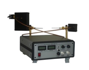
Ka-band Microwave Interferometer MWI 2650-A
Application
- Flame and combustion plasma
- Atmospheric pressure plasma jets (APPJ)
- Dielectric barrier discharge (DBD)
MWI 2650-A represents a microwave interferometer system adapted for measurements in plasma of medium and high pressure, namely > 5…20 mbar, when collision frequency of electrons with neutrals is comparable or more then the microwave frequency of the interferometer. The most of application, this version of the interferometer has in the atmospheric pressure plasma.
Microwave interferometry proved to be very efficient diagnostic for the thermal plasma of flames and combustion where not only electron density but also plasma temperature can be obtained (see below).
Another possible application is low gas temperature nonthermal atmospheric pressure plasmas, like corona discharges (CD), dielectric barrier discharges (DBD), atmospheric pressure glow discharges (APGD) and atmospheric pressure plasma jets (APPJ), which have been extensively studied in the last 20 years with regard to their application in materials processing, especially for surface modification (activation, cleaning and thin film deposition) and plasma chemistry (air cleaning, ozonisation, plasma synthesis). Compared to low pressure plasmas, they have the advantage that no expensive vacuum equipment is needed. However, the determination of a key plasma parameter, the electron density, of such atmospheric pressure plasmas is rather difficult. The traditional method in low pressure plasmas, the Langmuir probe cannot be applied in many cases, since there is no well established probe theory for the atmospheric pressure range. A non-invasive method suited for the plasma diagnostics of atmospheric pressure plasmas is emission spectroscopy. If the electron density is of the order of 1013 cm-3 or higher, Stark broadening of certain hydrogen atom emission lines (Balmer lines) emitted from the plasma can be used to determine the electron density. However, such electron densities are obtained in arc discharges, torches, etc, but not in low gas temperature plasmas. Thomson scattering might work for lower plasma densities than 1013 cm-3, but is a rather difficult technique which requires a lot of effort concerning the equipment and data evaluation. In summary, although microwave interferometry has also some difficulties in the nonthermal atmospheric pressure plasma due to small plasma size, which leads to operation at sensitivity limit, the microwave interferometer can be a reasonable alternative for diagnosis of such kind of plasma.
Technical Data
~ 1010 / l [cm], cm-3
when the plasma collision frequency is of the order of 26.5 GHz, e.g. thermal plasma (flame) and afterglow plasma.
~ 1011 / l [cm], cm-3
when the plasma collision frequency is one order of magnitude higher than 26.5 GHz, e.g. a nonthermal plasma with electron temperature of several eV (e.g. plasma jet)
l – plasma path length (plasma size)
Basics
Microwave interferometry of plasma is based on well known technique of investigation of dielectric properties of a medium with help of electromagnetic waves. Measurement of phase shift and absorption of microwaves in plasma gives a possibility to determine plasma density and collision frequency of electrons with neutrals. Both the phase shift and absorption can be measured by means of the microwave interferometer. The phase shift is measured by comparison of the microwave radiation phase in the primary transmission path of the interferometer crossing the plasma with a phase of radiation taken from an auxiliary transmission path coupled with the primary one and serving for a phase reference. The absorption can be obtained by measuring of an attenuation of the signal passed the plasma. With values of the attenuation and phase shift measured, the plasma density and collision frequency can be easily calculated. In the thermal plasma, the temperature can be additionally determined with help of Saha’s equation provided that the gas ionisation potential is known. Because of both measured signal are integrals along the transmission path of microwaves in plasma, all the measured values are averaged over the transmission path length. When plasma is large enough, radial distribution of plasma parameters in cylindrical plasma can be determined by making measurements at different position of lines of sight in normal to microwave beam direction and using then inverse Abel transformation.
Features
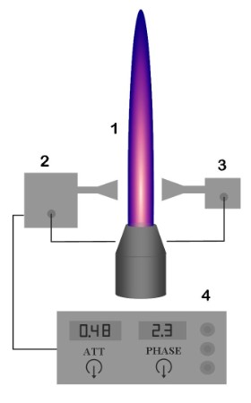 |
1 - plasma 2 - transmitter 3 - receiver 4 - control unit Fig. 2.1 |
The presented microwave interferometer MWI 2650-A is a ready-to-use device which does not demand any special knowledge to put it into operation.
Absolute value of line averaged attenuation and phase shift can be observed on displays and taken from BNC outputs after preliminary setting the system on zero before plasma is on (Fig 2.1). Display 'attenuation' can demonstrate also ratio of collision frequency to microwave frequency. Plasma density and electron-neutrals collision frequency can be then calculated by simple equations. Self-testing and errors identification functions increase reliability of measurements. The interferometer does not content rigid microwave waveguides for connections of interferometer parts. All the connections are made by flexible cables allowing easy setup and reinstalling of the system from one plasma installation to another.
High sensitivity of the interferometer, i.e. possibility of low density measurements is achieved by using frequency stable microwave oscillator and super-heterodyne receiving circuit. As a result, minimal density which can be measured in the CW plasma is determined mainly by a temperature drift of the zero level due to thermal expansion of the interferometer components rather then phase noise of the system. For transient plasma (also for switch on/off regime), where zero drift is not important, a value of the minimum detectable phase shift can be less then 0.1° and attenuation as low as 0.02dB can be measured.
Installation and operation
The interferometer includes two microwave units with antennas, one is emitting a microwave beam at 26.5 GHz, and the other acts as a receiver (Fig 2.1). For small size plasma, aperture of the receiving microwave antenna should correspond to plasma dimension. The interferometer uses for microwaves transmission a standard waveguide with cross-section of 7.2×3.6 mm, which defines the min aperture when an open edge of the waveguide is used as the receiving antenna. For smaller plasma, receiving microwave antenna should be customized. A few possible antennas designs for small size plasma are shown on Fig. 2.2.
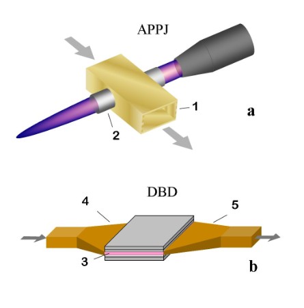 |
1 - waveguide 2 - dielectric tube 3 - plasma 4 - transmitting tapered horn antenna 5 - receiving tapered horn antenna Fig. 2.2 |
Cylindrical plasma of small diameter can be placed inside of a waveguide through a holes of appropriate diameter (Fig. 2.2 a), also using the tapered waveguide. For flat plasma of the DBD, tapered horn antennas can be used (Fig. 2.2 b).
Control unit of the interferometer contains digital displays for demonstration of values of attenuation and phase shift being measured, control buttons and BNC outputs. Standard version of the control unit contains the following service functions: fine adjusting to null for attenuation and phase, output filter with variable time constant, self-test and errors identification functions, calibrated BNC outputs of attenuation and phase for an oscilloscope or acquisition system, switch button of the attenuation display on collision frequency (as ratio to the microwave frequency).
Test measurements results
As examples of the MWI 2650-A application giving impression about minimum plasma parameters (plasma size, density, temperature) accessible for the system, results of two measurements in different plasmas are presented below.
| |
| Fig. 2.3 | |
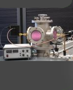
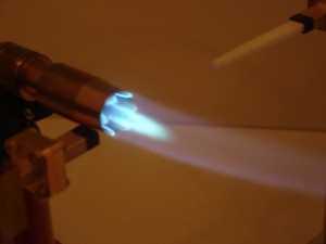
The first measurements have been carried out on flame of an usual Bunsen burner working with butane gas. Diameter of flame was about 1.5 cm. The open edge of waveguide serving as the receiving antenna was installed close to the plasma at the hottest part of the flame near the nozzle (Fig 2.3). Values of the phase shift and the attenuation measured are 0.12° and 0.02dB respectively. They give 8·109 cm-3 for density and 2.9·1010 s-1 for collision frequency. Using butane ionisation potential taken to be 10.6 eV, plasma temperature of 2300°K can be calculated from the Saha’s equation.
The MWI2650-A, has been also used to determine the plasma density of a single plasma jet. The plasma itself is produced by a cylindrical dielectric barrier discharge (DBD) in argon, operated at 15 kHz, a voltage of 7 kV (amplitude) and an argon gas flow of 5 slm. The plasma discharge diameter is about 6 mm in the discharge centre; its length downstream from the plasma jet exit nozzle is about 10 to 15 mm. The plasma jet, i.e. the part of the discharge downstream from the plasma jet nozzle, was guided through an isolated part of a waveguide connecting the emitting and receiving antenna of the interferometer (see Fig 2.2 a). The cylindrical tube in the waveguide had an inner diameter of 0.16 cm. Measured values of attenuation and phase: 0.02dB and 0.2° give density: 1011 cm-3 and collision frequency: 1,8·1010 s-1. The low value of the collision frequency is probably explained by that main contribution in the interferometer signal is given by afterglow plasma.