Ka-band Microwave Interferometer MWI 2650
Application
- Characterisation of technical plasma
- Process development and control
Microwave interferometer MWI 2650 is a basic version of the Miwitron interferometers family. It is intended for electron density measurements in plasma installations with evacuated vessels where gas pressure does not usually exceed 5…20 mbar.
The interferometer can find application in the fundamental plasma physics research carried out on the 'cold' laboratory plasma as well as in the Plasma Technology for characterisation and control of the technical plasma used for plasma etching, plasma deposition, etc. (see Application Notes).
Basics
Microwave interferometry of plasma is based on well known technique of investigation of dielectric properties of a medium with help of electromagnetic waves. Due to the fact that the dielectric constant of plasma is determined by plasma parameters, measurement of the propagation characteristics of microwaves passed the plasma gives a possibility to obtain plasma density.
Microwave interferometer measures phase shift of microwave radiation produced by plasma placed in the primary transmission path of the interferometer in respect to a phase of a radiation taken from an auxiliary transmission path of the interferometer serving for the phase reference. In the low pressure plasma, this phase shift is essentially a function of plasma density only. Since the shift in phase can be calibrated, one has a continuous measurement of density between the upper limit of strong refraction effects near the plasma critical density and the low limit of phase sensitivity of the interferometer. This technique is ideally suited to the observation of density as a function of time. Because of measured signal is integral along the transmission path of microwaves in plasma, the value of density determined is averaged over the transmission path length.
Technical Data
in pulsed (transient) plasma: (109 – 1010) / l [cm], cm-3
in CW (stationary) plasma: (1010 – 1011) / l [cm], cm-3
l – plasma path length (plasma size)
The operating frequency determines the range of electron density which can be measured with the microwave interferometer. The chosen operating frequency covers maximum of possible applications of the interferometer.
The maximum density is defined as ~1/3 of the critical density.
The minimum density is determined by the threshold sensitivity of the interferometer. This value is given with interval in one order of magnitude because of it depends on measuring conditions. Besides, it is different for continuous and pulsed plasmas. In continuous (CW) plasma, minimum density is determined by a temperature drift of the zero level of the interferometer due to thermal expansion of the interferometer parts and vacuum chamber. For pulsed plasma, where temperature drift is not important, the minimum density can be at least one order of magnitude less. In case when CW plasma can be turned off for a shot time during operation, the minimum density is the same as for pulsed plasma.
The maximum temporal resolution depends on plasma density being measured and for density less then (5·1012 / l [cm]) cm-3, it is about 1μs. For higher density, temporal resolution can be characterised as a maximum grow rate of density
Δn/Δt = (2·1011 / l [cm]) cm-3 μs-1.
The maximum gas pressure limit is determined by collision frequency of electrons with neutrals. For correct measurements, collision frequency should be in a few times less then the operating frequency of the interferometer. Collision frequency and hence maximum gas pressure are different for different gases and gas mixtures, but for pressure less then a few mbar collisions are definitely not important for all gases.
Features
The presented microwave interferometer MWI 2650 is a ready-to-use device which does not demand any special knowledge to put it into operation.
Absolute value of line averaged plasma density can be observed on displays and taken from a BNC output after entering in the system a value of the plasma path length (plasma size) and preliminary setting the system on zero before plasma is on.
Self-testing and errors identification functions increase reliability of measurements.
The interferometer does not content rigid microwave waveguides for connections of interferometer parts. All the connections are made by flexible cables. It allows very simple reinstalling of the system from one plasma reactor to another with any given distance between microwave antennas.
High sensitivity of the interferometer, i.e. possibility of low density measurements is achieved by using of relatively low microwave frequency 26.5 GHz, frequency stable microwave oscillator and super-heterodyne receiving circuit. As a result, minimum density which can be measured in the CW plasma is determined mainly by a temperature drift of the zero level due to thermal expansion of the interferometer components rather then phase noise of the system. For pulsed plasma, where zero drift is not important, a value of the minimum detectable phase shift can be less then 0.1°. It depends also on intensity of filtration and averaging of the signal. High sensitivity allows performing of measurements in dusty and molecular plasmas where density is usually rather low and in case of low level of the discharging RF power.
Installation and operation
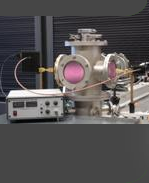
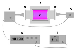
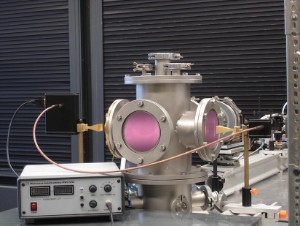
The MWI 2650 consists of two microwave units with antennas, one is emitting a microwave beam at 26.5 GHz, and the other acts as a receiver (Fig. 1.1, Fig. 1.3).
| |  |
vacuum chamber plasma dielectric windows transmitter receiver control unit oscilloscope / acquisition system
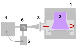
Fig. 1.1 | | plasma reactor plasma dielectric window transmitter receiver duplexer
Fig. 1.2 |
The plasma reactor should be equipped with two opposite dielectric windows transparent for microwave radiation. In case when plasma reactor does not have the second window which often takes place in industrial plasma reactors, one can use the circuit shown on Fig. 1.2. In this case, microwave radiation coming into the plasma through the one window is reflected from the opposite side of the chamber wall and come back trough the same window. The signal passed twice the plasma is received by the antenna which is used both for transmitting and for receiving and comes then via duplexer to the receiving unit.
Signal processing circuit of the interferometer provides measurements of the phase shift till 32π with it appropriate scaling to corresponding value of density.
| |
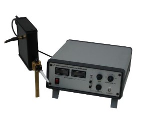
| Fig. 1.3 |
Control unit contains digital displays for demonstration of value of density being measured, control buttons and BNC outputs. Standard version of the control unit contains the following service functions: calibration of the system by entering value of plasma path length (plasma size); fine adjusting to null, output filter with variable time constant, self-test and errors identification functions, indication of phase shift increase over 2π, calibrated BNC output for an oscilloscope or acquisition system, received signal strength indicator (RSSI) output. The latter can be used at the installation of the interferometer for adjusting of microwave antennas by maximum of the received signal. The RSSI output can be also used for measurements of absorption of microwave radiation in high pressure (> 10mbar) plasma. It makes this version of the interferometer in principle applicable for all pressures of plasma.