Ka-band Microwave Interferometer MWI 2650-V
Application
 The MWI 2650-V is a two channel interferometer system. Besides its standard application for electron density measurements, it allows also measuring of plasma stream velocity. The interferometer can be also helpful for investigation of flow instabilities. The system can find application in such areas as supersonic and hypersonic high-temperature flows in the wind tunnels, chemical (combustion) propulsion systems and electric propulsion systems (plasma thrusters). The interferometer is non-contact diagnostics having no parts exposed to the thermal attack of a flow and can therefore operate at any thermal condition of flow in the all pressure range. It is cost effective and simple in operation system which can serve as routine diagnostics of plasma flow electron density and velocity.
Also in the situation when application of the Langmuir probe is not a problem, the microwave interferometer can be useful, due to the fact that it gives definitely more reliable results for absolute value of averaged plasma density and can be used for calibration of the probe which can be in turn employed for density profile measurements. As the non-contact techniques, the microwave interferometer hardly has reasonable alternative for these applications. The other non-contact method for flow velocity measurements - spectroscopic techniques based on the Doppler shift of the absorption lines - faces significant physical and technical difficulties associated with availability of proper spectroscopic lines for a given gas and interpretation of results, being also more expensive and more complicated in use.
Technical Data
l – plasma path length (plasma size)
* the whole range; has to be customized for a range of interest.
** real time resolution determined by built-in cross correlation circuit. For velocity measurements in short-life (< 10ms) plasma, density fluctuation signals in channels should be stored by an acquisition system for the further analyses. In this case temporal resolution for velocity can be close to the fluctuations temporal scale.
Basics
Microwave interferometry of plasma is based on well known technique of investigation of dielectric properties of a medium with help of electromagnetic waves. Measurement of the propagation characteristics of microwaves passed the plasma gives a possibility to obtain plasma density.
Microwave interferometer measures phase shift of microwave radiation produced by plasma placed in the primary transmission path of the interferometer in respect to a phase of a radiation taken from an auxiliary transmission path of the interferometer and serving for the phase reference. In the low pressure plasma, this phase shift is essentially a function of plasma density only. In plasma of atmospheric pressure, collision of electrons with neutrals should be taken into account for correct density measurements. It can be done by measuring additionally absorption of microwave radiation in plasma.
Since the shift in phase can be calibrated, one has a continuous measurement of density between the upper limit of strong refraction effects near the plasma critical density and the low limit of interferometer's sensitivity. This technique is ideally suited to the observation of density as a function of time.
Time resolved measurements of density fluctuation existing in any plasma flow give possibility to determine the velocity of the flow. For this purpose, measurements of density fluctuation should be carried out simultaneously in two interferometer channels shifted at some distance along the plasma flow. Delay of the signal in the downstream channel in respect to another one gives value of the flow velocity.
Because of measured signals are integrals along the transmission path of microwaves in plasma, all the measured and calculated values are averaged over the transmission path length. When plasma is large enough, radial distribution of plasma parameters in cylindrical plasma can be determined by geometrical scanning and inverse Abel transformation.
Features
The presented microwave interferometer MWI 2650-V is a ready-to-use device which does not demand any special knowledge to put it into operation.
Absolute value of line averaged plasma density and flow velocity can be observed on displays and taken from BNC outputs after entering in the system the value of the plasma path length (plasma size) and the distance between microwave beams.
Self-testing and errors identification functions increase reliability of measurements.
The interferometer does not content rigid microwave waveguides for connections of transmitting and receiving interferometer units. This connection is made by coax flexible cables which can be so long that distance between transmitting and receiving antennas can be several meters. It gives possibility to install the system on large installations like wind tunnels outside of the vacuum tank. This allows also easy setup of the interferometer on various plasma devices with any given distance between microwave antennas.
High sensitivity of the interferometer, i.e. possibility of low density measurements is achieved by using of relatively low microwave frequency 26.5 GHz, frequency stable microwave oscillator and super-heterodyne receiving circuit. High sensitivity allows performing measurements in flows with small electron density, for example - in the plasma wind tunnels with air as the working gas.
Installation and Operation
The MWI 2650-V system includes the basic version of the interferometer MWI 2650 and some additional equipment to build up two channels interferometer system for plasma flow velocity measurements (Fig 3.1).
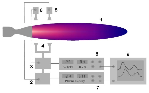 |
| 1 - plasma flow 2,5,7 - transmitting, receiving and control units of MWI 2650 3,6,8 - transmitting, receiving and control units of MWI 2650-A 4 - transmitting microwave antennas 9 - storage oscilloscope / acquisition system Fig. 3.1 |
Microwave radiation from the transmitting unit (1) of the MWI 2650 passes a microwave unit (2) of the second channel of the MWI 2650-V and is split then into two microwave beam by power divider (3). The receiving units (4, 5) of the system are connected with the corresponding transmitting units (1, 2) by coax cables.
For installing of the system outside of a vacuum vessel, it should be equipped with two pair of opposite dielectric windows transparent for microwave radiation in each transmission channel (four totally).
 | |  |
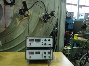
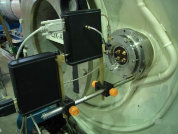
Installation of the interferometer outside of the chamber of the wind tunnel (DLR, Köln) Fig. 3.2 |
In case when an installation does not have enough windows, one can use the circuit similar to that described in the Installation and operation paragraph of the MWI 2650 and shown there on Fig1.2. In a situation when a chamber window is large enough, it can be used for both channels.
 | |
| Fig. 3.3 |
Finally, it is not much more difficult to install the microwave antennas of the system inside of the chamber. In this case, only one port for coax vacuum feedthroughs (can be included) is needed. The latter option is also preferable when the system is intended for routine monitoring measurements.
Control unit (6) includes two boxes. One of them is identical to the MWI 2650 control unit and intended for registration of plasma density in the first channel (see Installation and operation of the MWI 2650 for more detailed description of functions). The other one relates to the second transmission channel and is intended for registration of the plasma flow velocity as well as electron density in the second channel.
The system allows simultaneous observation of density fluctuation signals in each of the interferometer channels in frequency range till 1 MHz.
Value of the flow velocity is inferred from the density fluctuations signals in two transmission channels by the cross correlation analysis of the signals. Obtained values of flow velocity and correlation amplitude as well as plasma density in the second channel can be shown on the digital displays of the control box and have BNC outputs for an acquisition system
Application Note
The interferometer has been applied on the 1MW arc-heated wind tunnel L2K of the Institute of Aerodynamics and Flow Technology, Supersonic and Hypersonic Technology
of the German Aerospace Centre in Cologne ( Head of the Department: Dr.-Ing. A. Gulhan).
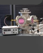
The wind tunnel is supplied with two pair of opposite windows of 10 cm diameter and spaced 38 cm along the flow direction. It gave opportunity to install the microwave antennas outside of the vacuum chamber (see Fig. 3.2). Distance between transmitting and receiving antennas in this case was about 3 meters.
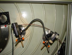
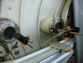
Later, the microwave antennas were installed inside of the chamber using coaxial vacuum feed-throes in one of the windows (Fig. 3.3). Microwave antennas in this case were placed close to the flow with distance between transmitting and receiving antennas 70 cm and spacing between microwave beams along the flow 20 cm.
Measurements have been done with Argon and Air as working gases. They have demonstrated rather high level of density fluctuation in the flow which can be used for reliable measurements of flow velocity. Correlation between channels was about 80%. In experiment with Argon, at arc current of 300A and enthalpy of 2 MJ/kg, electron density of 4·1013 cm-3 and flow velocity of 2 km/s have been measured. In Air, at the arc current of 900 A and enthalpy 15 MJ/kg, electron density and flow velocity are 2·1010 cm-3 and 3.5 km/s respectively.